All Arduino users are familiar with “digitalWrite”. This is just one of the built-in functions that have made the Arduino an easy to use device. This particular function was built to reduce the burden of the software details of working with hardware and to generalize input/output across a variety of different parts.
But, do you know the consequences of using this type of function? The following is a simple program, similar to the the example program that everyone 1st run on their board. This program doesn’t do any explicit delay from turning on an output to when an output is turned off.
void setup() {
pinMode(2, OUTPUT); // LED on board
}
void loop() {
while(1) {
digitalWrite(2, HIGH);
digitalWrite(2, LOW);
}
}
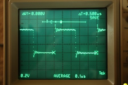
The program is simple enough. Here is the waveform produced on pin #2 (16MHz Arduino board).

The waveform high time is about 3.3usec (~53 clock cycles) , the low time is about 3.45usec (~55 clock cycles, picture is not shown), and a pulsing frequency of ~148KHz. Now let’s change the program to something a bit more difficult to understand, but more efficient
void loop() {
while(1) {
PORTD |= _BV(2);
PORTD &= ~_BV(2);
}
}
Now the high time is only 125ns (only 2 clocks), the low is 251ns (only 4 clocks), and a pulsing frequency of 2.7MHz. This is considerably faster.


The GNU compiler that is used for the Arduino IDE optimizes the “PORT |= _BV(2)” to a single instruction “SBI”, while the other operation is converted to a single instruction “CBI”, each taking 2 cycles.
The primary difference between the first and second approaches is flexibility and portability. The “digitalWrite” is more portable and the pin parameter is a variable, while the second approach is a fixed pin parameter (at compile time) and you have to know the port group (PORTB, PORTC, etc.). For example, the equivalent of “digitalWrite(13, HIGH)” is “PORTB |= _BV(5)” – you have to look at the schematic to see that pin #13 is on PORTBand is bit 5. Most often, the pin and port connections are frozen early in the design and this manual mapping isn’t a problem.
In addition, there is another not well known hardware feature for pins declared as OUTPUT. For those who don’t know, there are several registers associated with a port that are readable/writable. The most popular are the PORTx, which is used for output operations, and the PINx, which is typically used for input operations. But many don’t know that if you write to the PINx when the port is declared as output will toggle the current output value.
So, if I change the loop to the following:
void loop() {
while(1) {
PIND |= _BV(2);
}
}
Observe that the high and low times are exactly the same at 250ns each and the pulsing frequency is 2MHz.

I typically create a C macro to contain the operation, but you could also use an “inline” function. Using “inline” as a function modifier is another subject altogether.
for now…
Tags: Arduino
October 8, 2009 at 3:49 am |
[…] That weird-looking line takes advantage of an Arduino hardware feature: if you write a 1 to a bit in the PIN register, the corresponding PORT value toggles. It’s documented in The Fine Manual on page 74, section 13.2.2 and mentioned there. […]
October 8, 2009 at 7:20 pm |
Yeah – that technique was first developed in about 1975 and used for several embedded microprocessors. The purpose of the post was to help those who either don’t have the time to read the thick manual or don’t understand it.
December 8, 2009 at 10:01 pm |
I wrote some code that wraps all of this in templates. Now you can write digital_write(HIGH) instead of PORTB |= _BV(4). The code is available here: http://pastebin.com/f5769c4f1. The code uses this pin mapping: http://arduino.cc/en/Hacking/PinMapping168.
Thanks for this post.
December 7, 2013 at 5:56 pm |
“PIND |= _BV(2);” , “PORTD |= _BV(2);” and “PORTD &= ~_BV(2);” all take 125ns, the extra 125ns comes from the “while (1)” loop. If you would just write the same thing over and over again, it would be even faster.
October 20, 2015 at 9:01 am |
[…] takes a whopping 52-55 cycles to change pin direction! [image source]Are there benefits to invoking the hardware directly? Absolutely. A few curious inquirers before us […]
October 20, 2015 at 12:10 pm |
[…] digitalWrite takes a whopping 52-55 cycles to change pin direction! [image source] […]
February 3, 2016 at 2:07 pm |
Nice article, minor typo: PORTB |= _BV(6) for pin 13, not _BV(5), starting at bit 1 for pin 8.
February 9, 2016 at 6:38 pm |
Erwin, the definition of the Arduino macro “_BV” is such: “#define _BV(bit) (1 << (bit))". This means we start with bit = 0 which gives a mask of 0x01, so bit = 5 will give a mask of 0x20, which selects "pin 13".
Indexes in hardware start with 0 not 1. A byte has bits 0 through 7 not 1 through 8
bill